
Introduction to Gazebo
Aug 12, 2020
Getting started with basics of URDF to create you own simulations!
Introduction
Gazebo is a great tool that can be used for the simulation of robots. Many people who are new to ROS , often are not able to understand Gazebo properly , and rely on pre-made robots like turtlebot , husky , etc .. These simulations are great! , but if you do not understand atleast the basics , then you will have a hard time figuring out how to add any modification to the robot! If you are at this stage , then we are there to help you out!!! So let’s dive in!
Basic File Structure:
We are going to use the URDF format for specifying all of our robot elements. There is a long ongoing debate on wheather it is good to use the SDF or the URDF format for robot simulations!. But since husky , turtlebot simulators use URDF file to specify robot elements , we are going to do the same. Note apart for the URDF files that have the .xacro extension , you might see some file with .gazebo format which we will talk about later in this blog
More about URDF
URDF stands for The Unified Robotic Description Format (URDF). It is an XML file format used in ROS to describe all elements of a robot.
We will use xacro for writing our URDF files.
- What is xacro ??
- Xacro (XML Macros) Xacro is an XML macro language. With xacro, you can construct shorter and more readable XML files by using macros that expand to larger XML expressions.
Now I will cover more about the different components of URDF files!
URDF Basics:
There are certain elements in URDF for describing robot’s dynamics. I am going to cover a few basic and essential elements.
<robot>element
This is the root element in the program. All of the other elements describing robot will be encapsulated within this element.
<link>element
The link element describes a rigid body in the robot. A rigid body in any simulation has 3 properties:
- Inertial
- Here you can specify the mass of the link
- You can specify the inertia values and they will be stored in a 3 * 3 rotational inertia matrix
- Let’s now see an example of the code
  <inertial>
         <origin xyz="0 0 0.5" rpy="0 0 0"/>
         <mass value="1"/>
         <inertia ixx="100"  ixy="0"  ixz="0" iyy="100" iyz="0" izz="100" />
  </inertial>
-
Visual Features
- Here you can specify how you rigid body will look
- Hence here you can specify geometry , like a box , a sphere etc.
- You can also meshes to give a look to your rigid bodies and it will be specified here only
- Lets’ also see an example of this
 <visual>
      <origin xyz="0 0 0" rpy="0 0 0" />
        <geometry>
          <box size="1 1 1" />
        </geometry>
        <material name="Cyan">
          <color rgba="0 1.0 1.0 1.0"/>
        </material>
 </visual>
-
Collision
- As the name sounds , this element helps you to specify the collision properties of the rigid body
- A colision element in a element will be converted into a 3D vector , in order to simplify the computations
- You can also use multiple collision element for a rigid body
- Let’s see an example of this
<collision>
       <origin xyz="0 0 0" rpy="0 0 0"/>
       <geometry>
        <cylinder radius="1" length="0.5"/>
       </geometry>
  </collision>
Putting it together
-
So Uptill now , our code structure will look something like
- We have a root robot element
- In that we will have different rigid bodies specified by links
-
Overall the follwing picture would be helpful to visualise the structure of a link
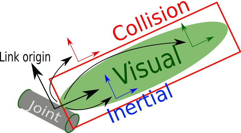
-
Joint
- This element describes the kinematics and the dynamic of the “joint”
- A joint in Gazebo is formed between parent link and the child link
-
A joint can be made as follows in the URDF File
<joint name="joint3" type="continuous">
       <parent link="link3"/>
       <child link="link4"/>
</joint>
- Following picture is good to visualize the point I am saying
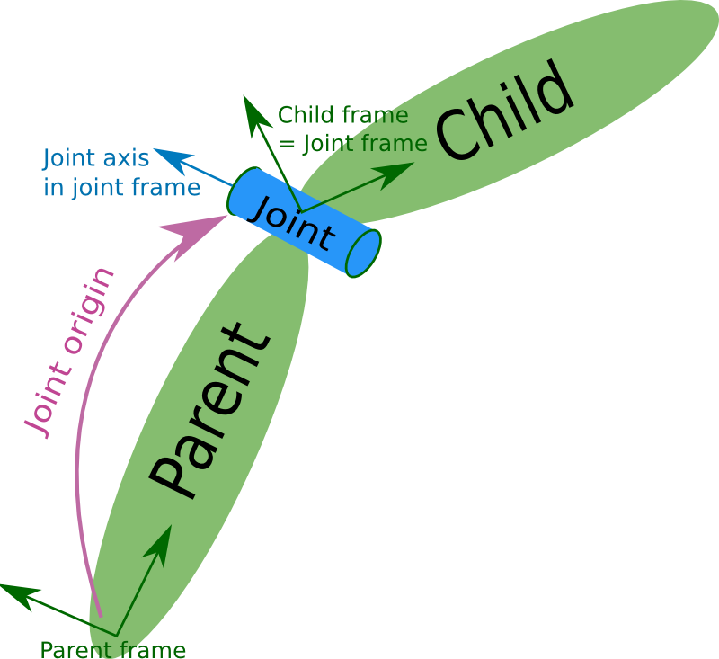
-
Gazebo
- Whatever is written in this element , will not be parsed by xacro
- Instead it will direcly be used by gazebo
- It is used to specify simulation properties such as color etc.
- Generally , these elements are store in the file with extension .gazebo that I told you about in the file structure module
These elements are enough to get you started ! You will be able to now construct anything you want to make in Gazebo! If you are anything like me , you will be probably asking , that these are just rigid bodies , but how to add functonalities to them?
Then ans is Plugins!
Gazebo has several builtin Plugins to use
- For example range plugin for the range sensor
- Diff drive plugin for the diff drive controller
- You can declare them , by just mentioning the body , you want to add functionalities to.
- Also remember to put them in a
tag , as they are specific to gazebo and wont be parsed by xacro - You can declare them like
<gazebo>
<plugin name = " " filename = " ">
</plugin>
</gazebo>
Now you can completely make your robot with sensor’s also!
Note:
- In order to launch this robot in gazebo just add robot description parameter in your launch file.
- Like
<param name="robot_description" command="$(find xacro)/xacro.py '$(find fb_description)/urdf/fb.xacro'"/>
As an example you can look at the simulation made by us here at Team ARES
- It has a skid drive controller and We have added a realsense camera , IMU etc. sensors to it
- Made with ♥ by Team ARES